Ac To Dc Converter Matlab

Ac Dc Three Level Pwm Converter Matlab Simulink

Ac To Dc Converter Matlab Simulink Simulation Complete Tutorial

Ac Dc Ac Converter Matlab Simulink

Ac To Dc Converter In Matlab Simulink Youtube

Three Phase 3 Q Ac To Dc Converter Using Thyristor By Matlab

Solar Power Converter Matlab Simulink

Controller driven bidirectional dc dc step up and step down voltage regulator.
Ac to dc converter matlab. The 600v 60 hz voltage obtained at the secondary of the wye delta transformer is first rectified by a six pulse diode bridge. Alternatively the converter can support regenerative power flow from load to supply. The 600v 60 hz voltage obtained at the secondary of the wye delta transformer is first rectified by a six pulse diode bridge.
A 60 hz voltage source feeds a 50 hz 50 kw load through an ac dc ac converter. Simulink is used to develop the models of ac to ac converters presented and the book is mostly suitable for researchers and practicing professional engineers working in the area of ac to ac converters. Learn how to model and simulate dc dc converter in simulink and simscape electronics.
The filtered dc voltage is applied to an igbt two level inverter generating 50 hz. Use the simulation model to size passive components calculate power losses design digital pid controller and implement it on ti tms320f28035 microcontroller. Ac to ac converters.
Web browsers do not support matlab commands. The dc dc converter block represents a behavioral model of a power converter. The dc voltage is back to 500 v within 1 5 cycle and the unity power factor on the ac side is maintained.
Average value bidirectional ac dc voltage source converter. To balance input power output power and losses the required amount of power is drawn from the supply side. This power converter regulates voltage on the load side.
We can see that the dc voltage drops to 315 v. Modeling simulation and real time implementation using simulink provides a summary of ac to ac converter modelling using matlab. At t 100 ms a stop pulsing signal is activated pulses normally sent to the converter are blocked.

Single Stage High Power Factor Ac Dc Converter File Exchange

3 Phase Inverter File Exchange Matlab Central

Hysteresis Controller Based Dc Ac Inverter File Exchange

Three Phase Ac Dc Ac Pwm Converter File Exchange Matlab Central

Matlab Model Of 36 Pulse Ac Dc Converter Fed Dtcimd Download

Simulation Of Single Phase Full Bridge Inverter Using Matlab

Matlab Model Of 72 Pulse Ac Dc Converter Fed Dtcimd Zero Sequence
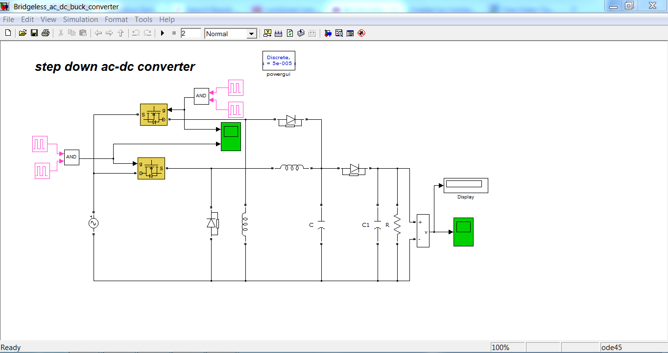
Bridgeless Ac Dc Buck Converter

25 Level Inverter Using Sub Multilevel Cells File Exchange
Dc To Ac Full Bridge By Inverter File Exchange Matlab Central

Push Pull Dc To Ac Converter File Exchange Matlab Central
How To Make Bi Directional Ac To Dc Power Converter On Matlab

Single Phase Pwm Inverter Matlab Simulink
